This note deals with the way in which power flow in an electromagnetic medium is quantified. The Poynting vector is the primary tool used for this purpose. If the electric and magnetic field phasors are given by \(\vec{E}\) and \(\vec{H}\), respectively (revise here in case you forgot phasors), the complex Poynting vector is simply defined as: \(\vec{S} = \vec{E} \times \vec{H}^*\), with units of \(W/m^2\) and the average power is defined as \(S_{av} = \frac{1}{2} Re(S)\). Recall that this is quantity averaged over one time period. From here on, we will work only with phasors.
Single medium
For a plane wave travelling in a medium, with electric field as \(\vec{E} = E_i \exp(-j\vec{k}\cdot\vec{r}) \hat{e} \), we derive the magnetic field from Maxwells equations as \(\vec{H} = \frac{1}{\eta_1} E_i \exp(-j\vec{k}\cdot\vec{r}) (\hat{k}\times\hat{e} )\), where \(\eta_1=\sqrt{ \frac{\mu_1}{\epsilon_1}}\) is the intrinsic impedance of the medium. With this, we get average power as \(S_{av} = \frac{1}{2\eta_1} |E_i|^2 \hat{k}\).
Now, what if there are two waves travelling in a medium but in opposite directions, i.e. \(\hat{k}\) and \(-\hat{k}\)? Say that the first wave has electric field \(\vec{E}_1 = a \exp(-j\vec{k}\cdot\vec{r}) \hat{e}_1 \) and the second one \(\vec{E}_2 = b \exp(j\vec{k}\cdot\vec{r}) \hat{e}_2 \). Can we directly write the net Poynting vector as \(S_{av} = \frac{1}{2\eta_1}(|a|^2 - |b|^2) \hat{k}\)? This is a tricky question and will be explored in depth later. But let’s verify if it is true by going to the basic definition of Poynting vector. These are the net electric and magnetic fields:
Thus, the net Poynting vector is:
Why did the last two terms in \(\vec{S}\) not survive in \(S_{av}\)? Note that for both waves, \(\vec{E},\vec{H}\) are in a plane perpendicular to \(\hat{k}\), and that \(\hat{e}_1\times\hat{h}_1 = -\hat{e}_2\times\hat{h}_2\). Let’s say the angle between \(\vec{E}_1,\vec{E}_2\) is \(\phi\). Since \(\vec{H}_1,\vec{H}_2\) are perpendicular to these vectors and in the same plane, it can be seen via simple diagrams that the angles between \(\hat{e}_1,\hat{h}_2\) and \(\hat{e}_2,\hat{h}_1\) will both be \(90-\phi\). Finally, we will also have \(\hat{e}_1\times\hat{h}_2 = -\hat{e}_2\times\hat{h}_1\). Thus, the last two terms will be of the form \(z-z^*\) which is a purely imaginary number and does not contribute to \(S_{av}\). So, we were correct in our intuition of superposing the Poynting vectors regardless of the polarization of the individual fields. Later on, we will find this idea of superposition of Poynting vectors to not be true in general.
Two mediums
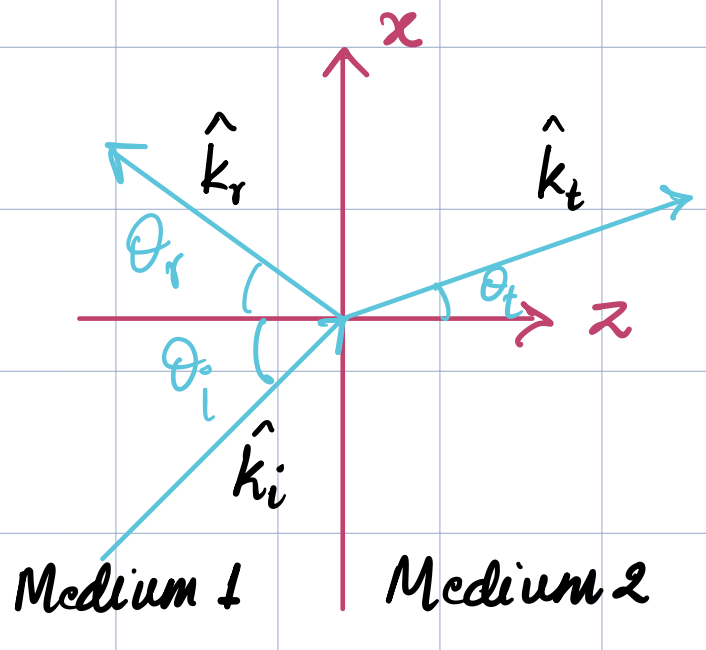
Now consider two mediums with an incident wave with electric field amplitude \(E_i\) at angle \(\theta_i\) hitting the interface and let \(\theta_t\) be the angle of the transmitted wave with electric field amplitude \(E_t\). Let the interface be characterized by the normal vector \(\hat{z}\), as shown in the figure below.
In medium 1, the net power is given as \(\vec{S}_1 = (\vec{E}_i+\vec{E}_r)\times(\vec{H}_i+\vec{H}_r)^*\), consisting of the incident and reflected fields, while in medium 2 it is simply \(\vec{S}_t=\vec{E}_t\times \vec{H}_t^*\).
Let’s explore the Poynting vector in medium 1. For simplicity, let’s consider perpendicular polarization, with \(\vec{E}\) being along \(\hat{y}\) and propagation directions as \(\hat{k}_i = (\sin\theta_i,0, \cos\theta_i)\) and \(\hat{k}_r = (\sin\theta_i,0, - \cos\theta_i)\). The individual Poynting vectors are given by \(\vec{S}_i = \frac{|E|_i^2}{2\eta_1}\hat{k}_i\) and \(\vec{S}_r = \frac{|R_{\perp}E|_i^2}{2\eta_1}\hat{k}_r\). What about the net Poynting vector? We work with the net electric and magnetic fields:
Note that \(\hat{y} \times \hat{h}_i = (\sin\theta_i,0,\cos\theta_i) \), and \(\hat{y}\times \hat{h}_r= (\sin\theta_i,0,-\cos\theta_i) \). Thus, the net Poynting vector in medium 1 is:
The first important conclusion is that the net Poynting vector is not a superposition of the two individual Poynting vectors, i.e. \(\vec{S}_i + \vec{S}_r \neq \vec{S}_1\), unless something special happens to make the last two terms of \(\vec{S}_1\) vanish. This is not a surprising result since the Poynting vector is not a linear experssion in terms of fields, so we should not expect superposition to hold.
Moving on to medium two, the fields are as follows:
This gives the net Poynting vector as:
Now, consider a tall rectangular cuboid, straddling the interface midway, with the width (in \(z\)) and depth (in \(y\)) of this box tending to zero as shown in the figure below.
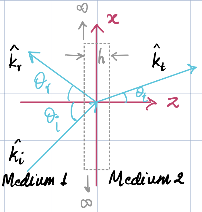
We apply the Poynting energy conservation theorem on this box. Since the media are lossless, whatever power travels along the normal to the long sides of the box, i.e. along \(\hat{z}\), must be conserved. So we should have the following hold true, regardless of polarization:
We can verify this is true by referring to the usual Fresnel coefficients as well:
Plugging in these coefficients into the equation above them shows the following for both polarizations:
where the denominator changes depending on the polarization but is the same for LHS and RHS.
Thus, the power flux is conserved in the direction normal to the interface in the case of lossless media. The claim \(|R|^2+|T|^2=1\) seen in many references is not true in general, unless the other terms in the above expression manage to cancel off, i.e. unless \(\eta_2 \cos\theta_i = \eta_1 \cos\theta_t\). The above discussion also shows that when speaking about power density, it is important to specify the direction because the Poynting vector is just that, a vector. If a direction is not specified, then a common assumption is to assume it to be the direction of propagation. For e.g. if we ask, what is the power density of the transmitted wave? It usually refers to the magnitude of the Poynting vector along the direction of wave propagation, i.e. \(\hat{k}_t\).
A simple example helps us grasp the idea: Consider a planewave with 1W (average) power density that is incident from air on a non-magnetic medium with relative permittivity \(\epsilon_r = 3\) at \(\theta_i = 60^{\circ}\). From Snell’s law, this gives \(\theta_t = 30^{\circ}\), and the Fresnel coefficients are \(R_{\perp}=-0.5, T_{\perp}=0.5\). If individual Ponyting vectors are considered, we get \(S_i = \hat{k}_i W\), \(S_r = 0.25 \hat{k}_r W\), \(S_t = 0.25 \sqrt{3} \hat{k}_t W\). Clearly, trying to "conserve power" without taking directions into account leads to: \(1 \neq 0.25 (1+\sqrt{3})\), i.e. \(|S_i| \neq |S_r| + |S_t|\). Whereas if we consider power conservation in the direction normal to the interface, we get \(\vec{S}_1\cdot\hat{z} = 3/4 \times 1/2 = 3/8\), and \(\vec{S}_2\cdot\hat{z} = \sqrt{3} \times 1/4 \times \sqrt{3}/2 = 3/8\).
Three mediums
Let’s extend the discussion to the case of three media, with semi-infinite \(\eta_1\) on the left, a \(d\) thickness \(\eta_2\) in the middle, and a semi-infinite \(\eta_3\) to the right, and \(\hat{z}\) being normal to both the interfaces.
Further, let’s specialize to the case of normal incidence. We know that in this case there are infinite reflections within the second medium which gives rise to the expressions for the reflection and transmission coefficients to be the sum of an infinite geometric progression (GP). Let the incident electric field have magnitude \(E_i\). Let’s denote the net reflection coefficient back into medium 1 by \(R\), and the net transmission coefficient into medium 3 by \(T\). By "net" it is understood that the infinite GP has been taken into account. Also, there will be a partial standing wave in medium 2 and let the forward and backward wave amplitudes be \(aE_i\) and \(bE_i\) respectively.
Again, conserving power normal to the interface (i.e. \(\hat{z}\)), we get the following expressions for the average Poynting vector in each medium, which must all be equal:
There are three ways of computing the terms \(R,T,a,b\) in this problem: the infinite GP approach, the transmission line analogy (which doesn’t give all the terms, only \(R, |T|, |a|^2-|b|^2\)), and a transfer matrix approach which is the preferred way to solve this problem as the number of layers increases.
Back to the listing